Automatic Coupling Systems

Automatic Coupling Systems
Info:

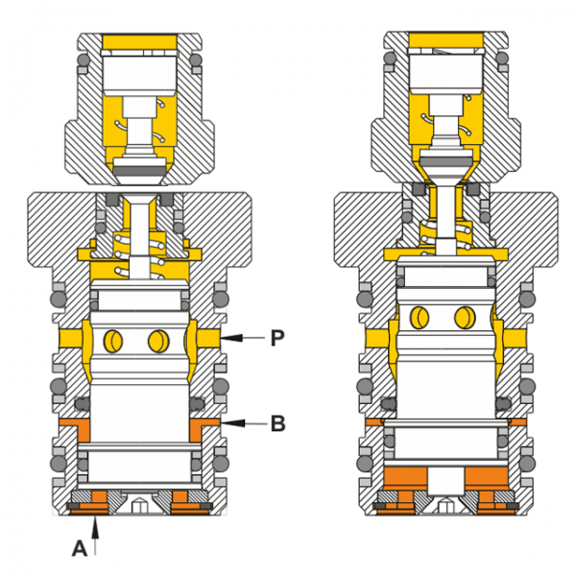
The coupling surfaces of the AKN and AKM are flat at the front so that the user can position them from any axial and/or radial position for coupling while maintaining the positioning tolerance. The coupling stroke is then performed by an integrated control piston A. It is possible to specifically control individual clutches. The control pressure A should be pressurized with the same pressure as the medium pressure P. When control port A is depressurized , the AKM is always in the home position. The maximum operating pressure is 350/300 bar. The AKM can be operated in double-acting or single-acting mode. If the AKM is operated in single-acting mode, port B must be used to ventilate the housing. To increase operational safety, double-acting operation is preferable

Special features:

  • No additional stroke required for coupling
  • Stainless materials and replaceable system seals
  • Patented coupling system
  • for transferring liquid/gaseous media and vacuum
  • Can be coupled without pressure or under pressure
  • Standard elements and special elements available
  • Targeted control of individual clutches possible
Nominal size:5, 8
Operating pressure:pmax. 350 (NW5), 300 bar (NW8)
Flow rate:max. 12 l/min (NW 5) / 25 l/min (NW 8)
Distance nipple/mechanism:0.6 -1 mm
Variant:Push-in and screw-in variants
Coupling method:pressureless or pressurized coupling
MediumLiquid, gaseous media and vacuum
Functional Principle:
automatic clutch system function diagram
1. positioning the coupling nipple to the coupling mechanism while observing the positioning tolerance
2. control connection A:
The connection to the coupling nipple side is established.
3. media pressure on connection P
Fig. left: AKM not actuated
Fig. right: AKM actuated